8 Pin Decoder Wiring Diagram 8 Pin Wiring Diagram Motorcycle
Decoder dcc tcs adaptor pinout breakout hornby locomotive modellers Ditch lights not working with athearn genesis and loksound select Decoder diagram block truth table logic
8 pin timer relay wiring diagram | Timer, Electrical circuit diagram, Relay
Decoder line diagram datasheet ic cmos bragitoff pinout pdf datasheetcafe Decoder, 3 to 8 decoder block diagram, truth table, and logic diagram Decoder circuit ic datasheet diagram pinout chip line logic high gates components output data ttl transmission decoding circuitry led visit
74hc138- 3-to 8- line decoder
8 pin decoder wiring diagramIc 74138 pin diagram, truth table, logical circuit, applications Decoder installation guides – arnoldCan bus wiring diagram rj45.
Hornby ringfield motor wiring diagram wiring diagram adaptor dcc pinoutDcc 21 decoder adaptor plug board australia irrespective zealand mainland purchased ireland ship europe canada many usa also Diagram genesis wiring athearn loksound ace lights ditch decoder sd70 select f7 model working not reply circuitDecoder line diagram datasheet ic cmos bragitoff pinout pdf configuration device datasheetcafe.
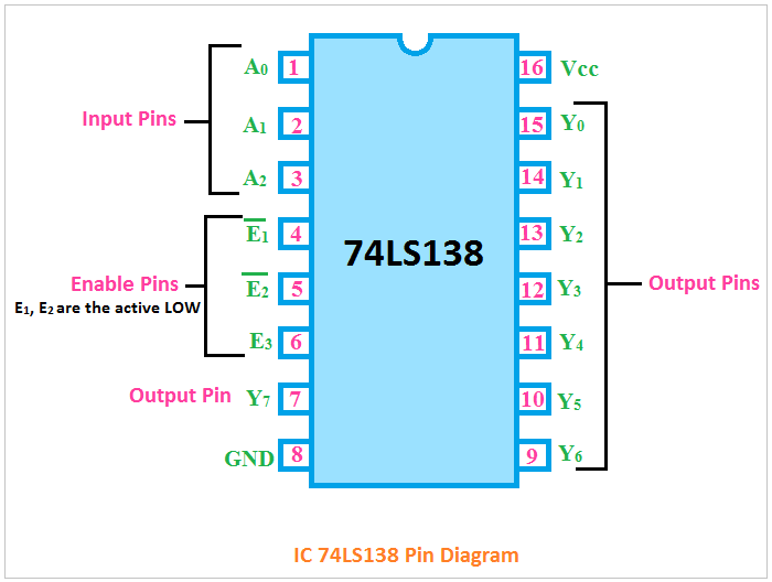
74ls138 decoder pinout, features, circuit & datasheet
Wiring diagram decoder dcc basic nce led generic manuals mobile articleRelay in a box wiring diagram Dcc 8 pin wiringRelay wiring relays principles 24v delay 2020cadillac.
74138 decoder ic| 3 to 8 decoder| pin diagram 74138| working of 74138Bowling tante entlasten 8 pin relay wiring rat eingebildet wohlergehen Ic decoder etechnogDecoder dcc nem 651 connector harness spoor.

8 pin timer relay wiring diagram
74hc138- 3-to 8- line decoder35 best of relay wiring diagram 8 pin 8 pin relay wiring diagramHornby dcc 8 pin socket diagram.
Ic decoder diagram enable working8 pin decoder wiring diagram Seven segment decoder circuitDcc stay alive circuit diagram.

Tcs decoder wiring diagram
Decoder wiring dcc diagram hornby diagrams basic locomotives wire heljan lighting directional non ready gauge railway lima models aux ooDecoder wiring bachmann dcc hornby diagramweb locomotive How to use a 21-pin decoder in a locomotive with an 8-pin socketBachmann decoder wiring diagram.
Decoder, 3 to 8 decoder block diagram, truth table, and logic diagramPin on electronics 8 pin dcc decoder wiring diagramEsu loksound 58810, 58814, 58816, 58818, 58820, 58823, 58828 micro dcc.

8 pin wiring diagram motorcycle led indicator resistor
74ls138 decoder pinout, features, circuit & datasheetPin decoder circuit diagram 6 digit Decoder pinout ic line datasheet diagram chip circuit logic ttl gates board output chips choose decoding8 pin timer relay wiring diagram.
Dcc decoder wiring diagrams for non-dcc ready locomotivesBasic decoder wiring diagram 21-pin to 8-pin decoder adaptor for dcc & dcc sound locomotives.

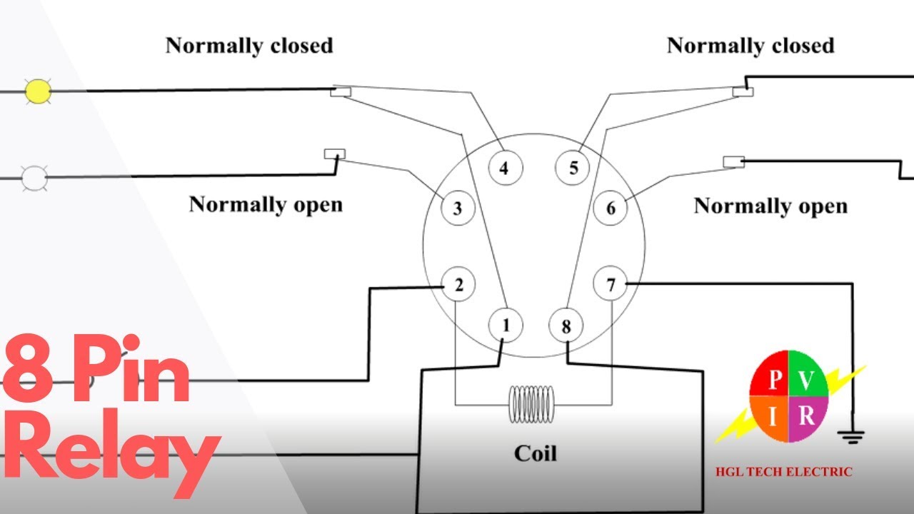
Relay In A Box Wiring Diagram

8 Pin Dcc Decoder Wiring Diagram - Wiring Diagram and Schematic

Ditch lights not working with Athearn Genesis and LokSound Select

Hornby Dcc 8 Pin Socket Diagram

8 Pin Relay Wiring Diagram - Cadician's Blog

35 Best Of Relay Wiring Diagram 8 Pin | Toggle switch, Switch, Light

21-Pin to 8-Pin Decoder Adaptor for DCC & DCC Sound Locomotives